
Shared technical information for design, fabrication and site teams
Models and shop drawings define geometry, connections, joints and tolerances. We coordinate the façade interfaces with the structure, building services and finishes.
RFIs and material submittals record decisions and approvals. Approved drawings define fabrication dimensions, fixing positions and installation information.
Concept studies · Generated illustrations
From coordination model to shop drawings
These concept visuals illustrate the types of decisions developed during design and coordination.
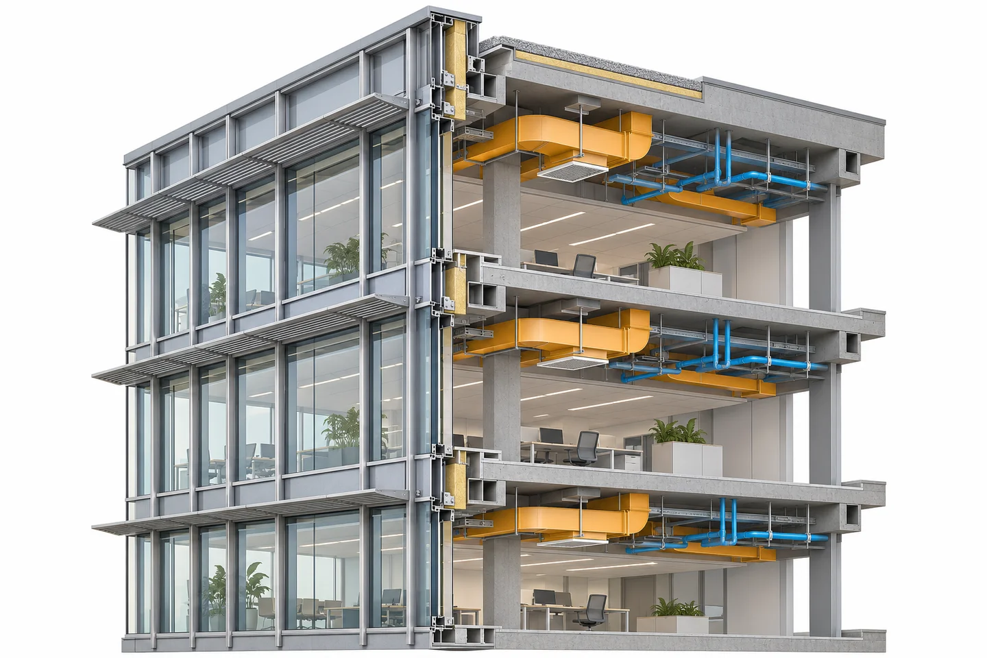
The model cutaway brings the façade, structure and building services into one view so zones requiring coordination can be identified early.
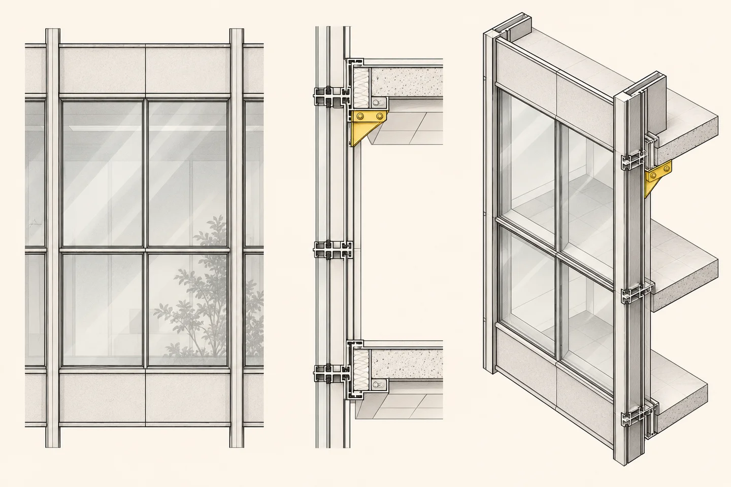
Three complementary views help the team cross-check component locations and interface geometry.
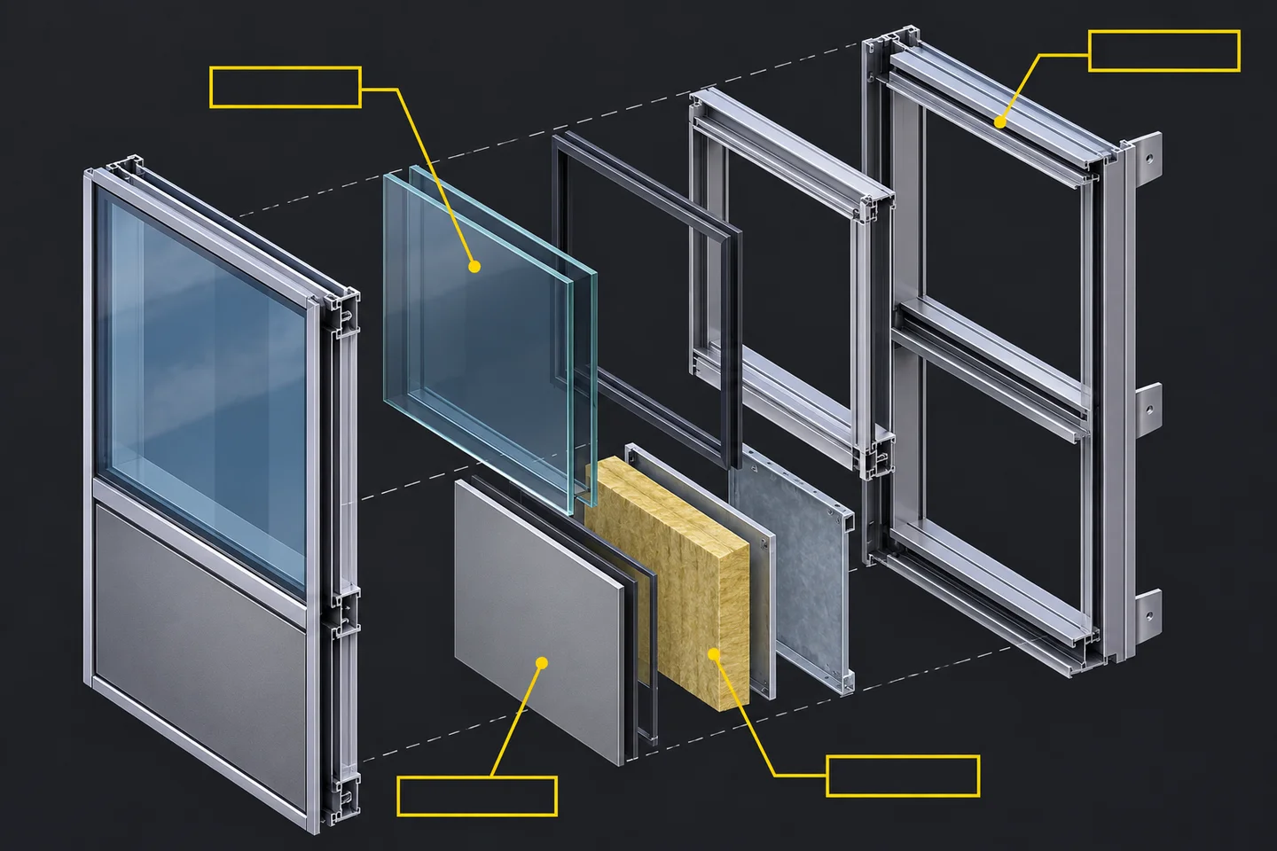
The exploded view links model geometry to the assembly sequence of the frame, glazing and opaque spandrel zone.
Illustrative scenario
Coordinating a mullion with a duct penetration
In the shared model, a proposed duct penetration overlaps a mullion fixing zone. The example follows the decision through to the issue of the shop drawing.

Identify
Clash location and disciplines involved
Deliverable
Coordination issue in the modelResolve
Revised penetration position and required clearances
Deliverable
Answered RFI and updated modelIssue
Agreed detail and revision in force
Deliverable
Shop drawing for approval
Fabrication receives the approved revision with a single reference for the mullion, bracket and duct penetration.